: Impact on astrometry : Wavefront corrugations before and : Error terms effected by 目次
For simulations of the StS calibration mode will be important to accuratly model the dependence of tip-tilt angle on wavelength and on the level of wavefront corrugation across the aperture plane in order to determine the following:
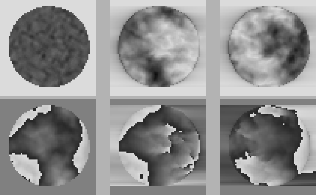
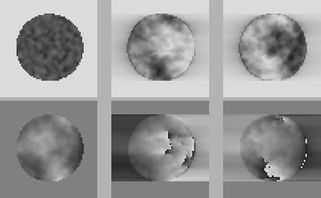
Although knife-edge or Schlieren wavefront phase detectors are widely used in astronomy (and microscopy), the effect of such a system on the optical phase at the image plane focus is not well documented. The phase perturbations introduced by the atmosphere will be partially converted into amplitude fluctuations in the pupil plane wavefront. Where the amplitude is very low, substantial changes in the wavefront phase may also be observed. In order to assess the impact of the StS roof mirror on interferometric observations, the simulations discussed in Section 3 were modified to include a knife-edge in the image plane. The pupil plane wavefront properties before and after the knife-edge in one timestep from the simulations can be seen in Figures 15 to 20. Figures 15 and 18 show wavefronts entering the StS for this timestep (identical to Figures 9 and 10, although the amplitude is plotted with a different greyscale). The effect of the wavefront corrugations in the input beam on the wavefront amplitude in the output beams is very strong - this is not surprising as the principle use of image plane knife-edges is in visualising wavefront corrugations (see e.g. [13,14]). These amplitude fluctuations are much larger than those produced by atmospheric scintillation, and may impede the fringe-tracking performance. Note that the knife-edge also diffracts a significant amount of light out of the beam.
 |
 |
It is clear that detailed simulations will be required in order to determine the expected optical phase and colour differences between the two beams output from the StS when it is operating in calibration mode. As the StS calibration mode represents the fundamental calibration of the PRIMA instrument, it will be important to estimate the phase difference expected between the two output beams in this mode. The two output beams will be swapped periodically using the de-rotator, so it will be important to look for effects which couple the differential phase in the output beams to the angle of the de-rotator.
Robert Tubbs 平成16年11月18日